![]()
Fabricating an Aluminum Intake Manifold for a Ford 2.3 liter turbocharged engine.
This is a remake of the previous intake manifold, this time in aluminum instead
of steel. I had been using a ported/polished iron head with oval inatke ports,
but recently changed to the Esslinger Aluminum "D" port head and
needed to have an intake that matched the ports on the head. Using the same
basic design parameters as the steel intake (medium runner length and diameter,
plenum about 80% of engine displacement) I decided to build this aluminum
intake. Since I recently purchased a TIG welder, I figured that I'd weld up
the intake myself. Lemme tell you, TIG welding aluminum is a different beast
altogether than welding steel with a MIG. It is much more difficult and requires
the utmost in fitment and cleanliness of the parts being welded. Also, since
aluminum has incredible heat conducting properties, it is imperative to pre-heat
large pieces when trying to weld with a barely adequate welder. All that being
said, here goes:
See http://www.majorleagueduning.com/tech/IntakeFabrication.htm for pics of
the previous steel intake.
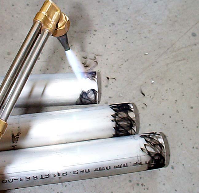 |
I measured the ports on the head and got some aluminum tube with an I.D. the same size as the upper port radius. I needed to flare the ends, so the aluminum had to be annealed, or softened, enough to allow this without cracking. Since aluminum melts before it gets red hot, an easy way to determine that you have reached the proper temp is to coat the aluminum with soot from an acetyline flame and then heat with a torch until the soot burns off. |
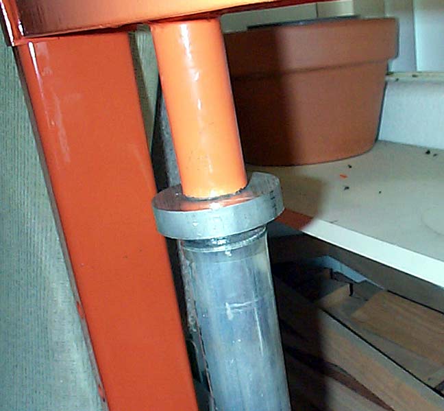 |
I used the die that I turned in the fab of the steel manifold to start the bellmouth on the aluminum tubes. Here's a shot of the die pressing the tube in the 20 ton shop press. |
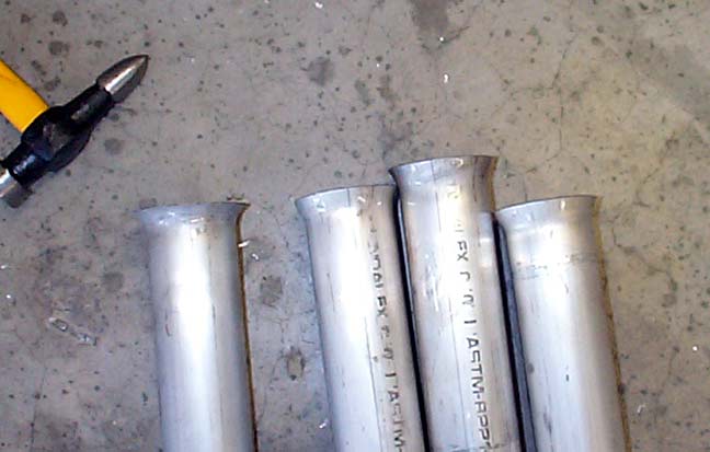 |
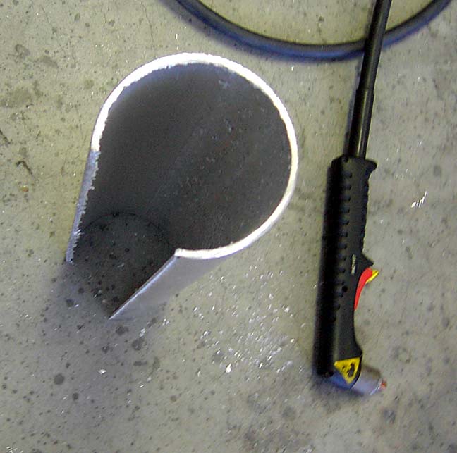
This is all the flare I could get without making another jig to hold the tubing (like a brake flare kit). No worries, aluminum is soft and I can finish the bellmouth with a hammer and dolly. |
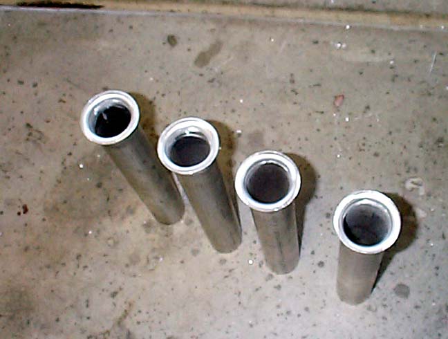 |
Here's the 4 tubes, flared and smoothed, ready for assembly. |
 |
For the plenum, I started with a 4" diameter tube and plasma cut a piece out of it. |
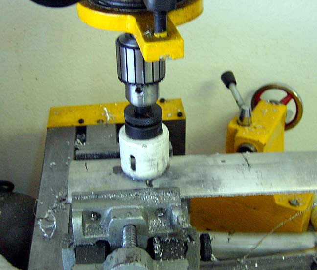 |
I put the piece that was cut out of the tube into a vice and drilled 4 correclty spaced holes for the tubes to go through. |
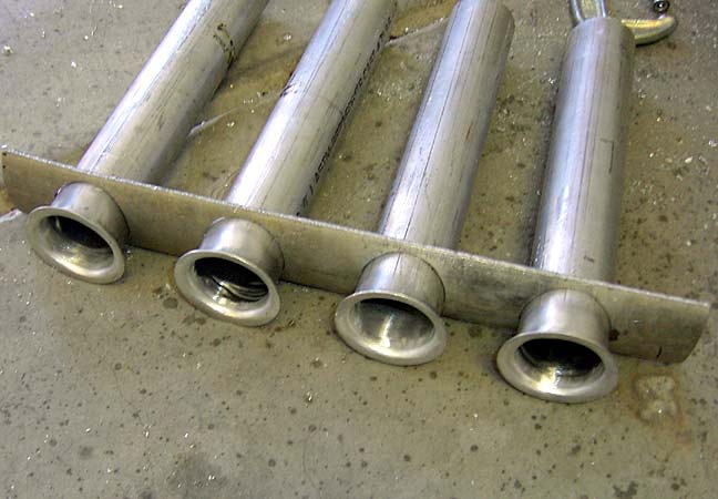 |
Here's the tubes protruding through the intake plenum piece. In order to have the flares on the inside of the plenum, and the tubes in one piece, this is how I had to make the plenum. |
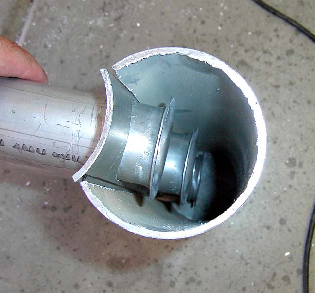 |
This is how the plenum will go back together. |
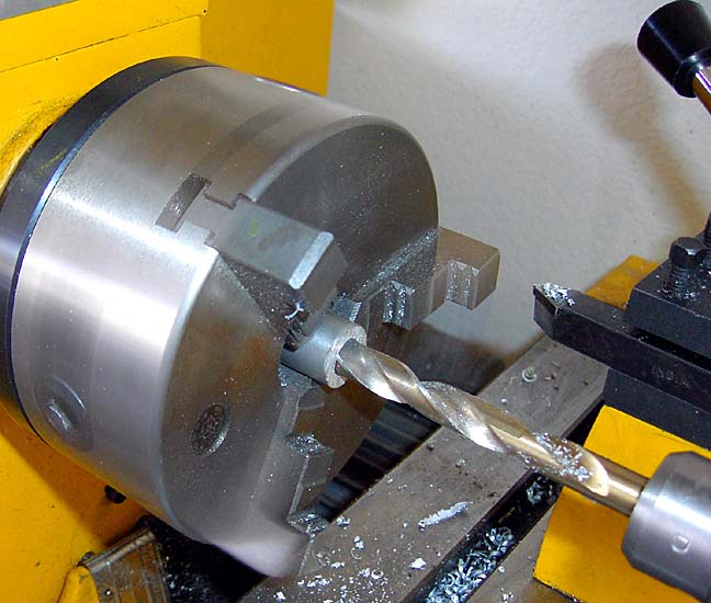 |
Drilling the bungs for the injectors was WAY cheaper than buying them. Just go slow, use lots of lubricant and you will have a nice, smooth custom injector bung for your intake. |
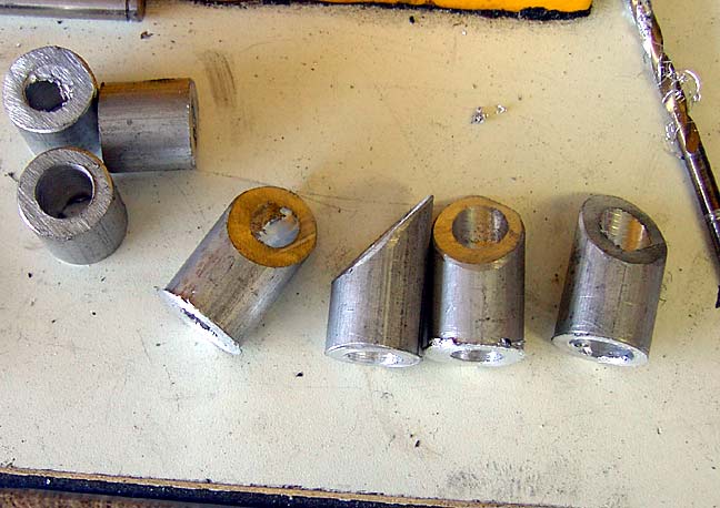 |
Here's the 4 bungs, cut at an angle and ready for welding |
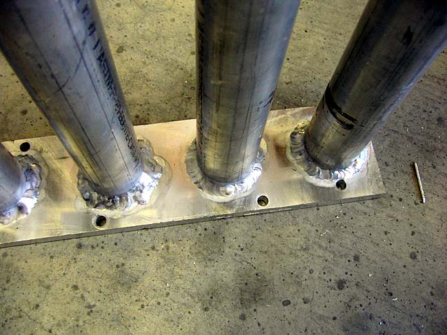 |
The tubes welded to the intake flange. I forgot to shoot pics of the fabbing of the flange, but it was pretty similar to the steel intake. I marked the location of the ports using the gasket, then drilled the center out and then used a die grinder with an aluminum bur to finish the shape. Valuable lesson here: USE OIL on the bur or it will load up and stop cutting after a few seconds. A squirt of cutting fluid avery few moments makes carving aluminum like carving butter. |
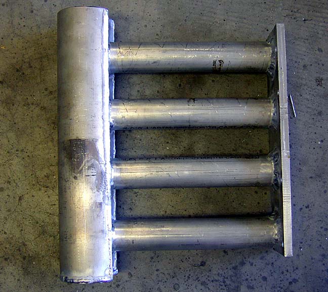 |
The mostly finished intake. Needs a tube/flange for the throttle body, injector bungs, and ports for the sensors. |
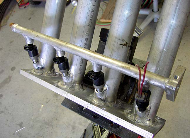 |
The mock-up of the fuel rail. The final rail has a return on the opposite side of the fuel feed. |
 |
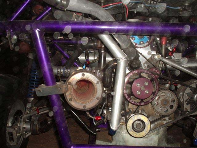
Here's the engine in the car - I don't have a pic of the intake side just yet, but I'll post one soon. |
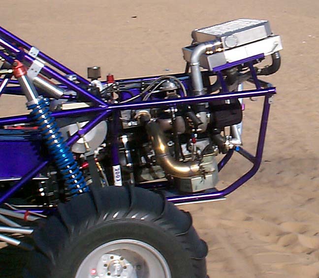 |
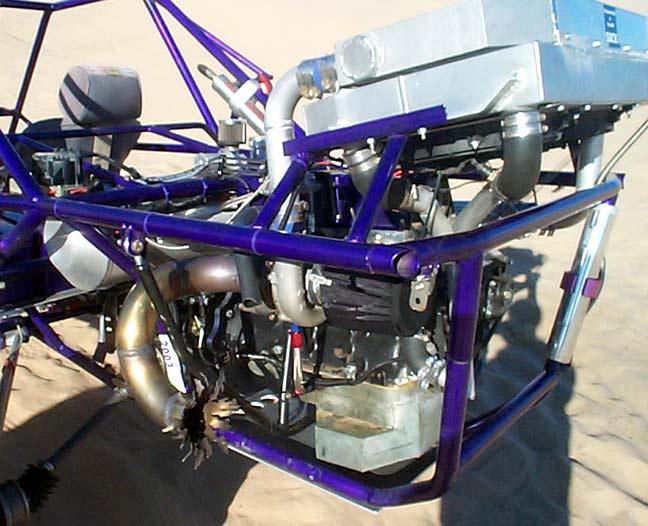
Another shot of the exhaust side. Spearco intercooler on top of radiator, Rod's header, 3" stainless exhaust, electomotive EFI, etc... |
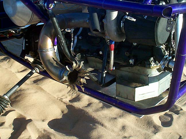 |
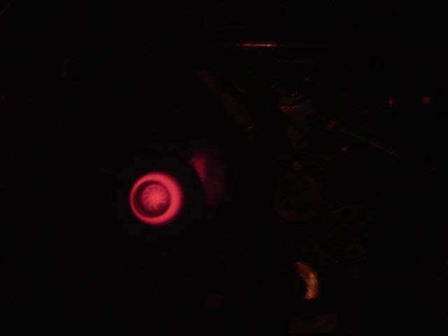
The header and turbo exhaust housing glow wicked red after a few passes up the hill, and with all the intense vibration common to inline 4 cylinders, especially in a solid-engine-mount situation, the Supertrapp flange kept cracking from fatigue. I decided not to gusset and bracket the muffler, and built the stainless pipe for fun. It gets a lot of comments, like. "DUDE! did that blow up?!" |
 |
This is the supertrapp on the car, unretouched, and you can see the glow inside the muffler. |
 |
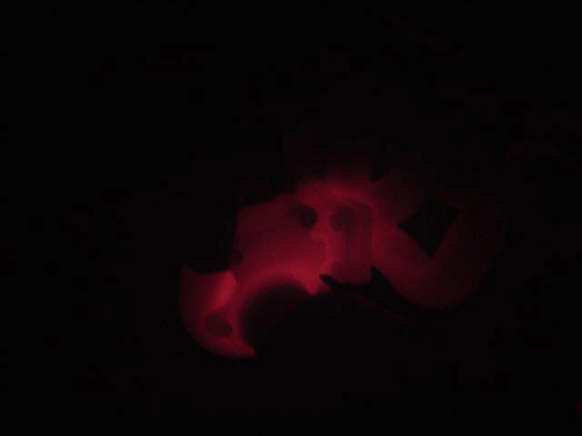
Same viewpoint, no flash. The engine was just turned off and you can see the glowing turbine. |
 |
Here's the turbine housing, header and part of the exhaust. Bitchin. Before you get all high-and-mighty, lemme tell you: according to a wideband o2 sensor and a 3 gas exhaust analyizer, coupled with spark plug inspection, the engine is running correctly. It is NOT too rich or too lean. There's just a ton of energy (in the form of heat) going through the engine. |
 |
Here's the top of Oldmobile Hill at Glamis, top of third gear, 83 MPH
according to the GPS (photo by Mark Stevens) |
 |
Us and Gary in the yellow rail. |
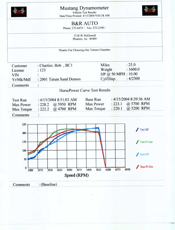 |
It's fun screaming past all those mazda and subaru powered rails with "400" horsepower, then when they ask what kind of power a Pinto makes, I say, "228" It is actually a bit more, but the dyno operator stopped the run shy of the 6800 RPM redline. At 6800 RPM, the 52 PPH injectors are hitting just over 80% duty cycle, so I figured it was a good place to limit the engine. I suppose I could jump up to 70+ PPH injecors and a larger fuel pump, and turn the boost up past 12 pounds, but I'm still running a bus tranny and until I can afford a Mendeola, I'll have to be happy with 228 RWHP. |