 |
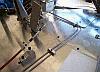
Brake line clamps and throttle cable clamp for the front
of the car. The brake line clamps have a rubber base to help
eliminate noise from vibrations. |
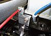 |
Here's a view of the throttle cable clamp on the engine. |
 |
The complete carburetor linkage and throttle cable. |
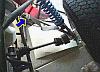 |
When the suspension is at full rebound, the c.v. joints
were binding so I had to add suspension limiting straps to prevent
the rear trailing arms from moving so far down that they would
damage the c.v. joints. |
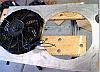 |
The radiator needs a fan or two and the fans need to be
mounted on a shroud that will direct the air through the radiator.
This is the beginning of the fan shroud. |
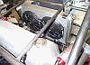 |
Here's the radiator and fans installed in the car. The
fans will be blowing hot air onto the gas tank, so I'll have
to add a small piece of aluminum to divert the air away from
the fuel tank. |
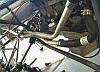 |
Gotta get the coolant from the engine to the radiator.
Here's a close up of the aluminum tube, mounting bracket and
hoses needed to plumb the radiator. |
 |
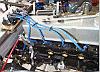
Here's the alternator belt tensioner, a radius rod. A radius
rod has heim joints on both ends and left-hand threads on one
end, so when the rod is rotated, the length increases or decreases
depending on the direction of rotation. In this case, it snugs
the belt nicely. |
 |
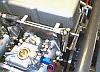
A distrubutor is too tall to work with the weber carburetors,
a more precise and tunable ignition is a crank-fire ignition.
The unit on the left of the picture is the crank-fire ignition
unit. It receives pulses from a proximity sensor and toothed
wheel on the crankshaft and fires a spark to the appropriate
cylinder |
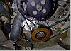 |
The highlighted area is the ignition trigger. Most new
cars use a similar type of ignition with many coils and no distributor. |
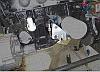 |
The distributor drive runs the oil pump, so I could not
totally eliminate the distributor. The highlighted area on the
left is an old ford distributor that I turned down in the lathe
and capped off so it will run the oil pump. The highlighted area
on the right is an engine mount that I machined out of a chunk
of aluminum. Larger radius rods will suspend the engine. The
rods are on back -order right now so the rest of the mount will
have to wait. |
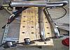 |
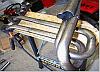
One of the most challenging things I have done on this
car is fabricating a header. The only headers available for a
rear mounted pinto engine are high-mount, they stick up above
the engine and almost 2 feet to the rear. Unacceptable.
After much research, I decided on a step-header design. The
tubes directly off the cylinder head are 1 3/8 inch diameter
and extend for 8 inches. The second step is tubes 30 inches long
and 1 1/2 inches in diameter. Here's the beginnings. |
 |
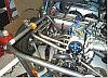
The tubes all have to be within 1/4 inch in length and
extend from the head to the collector. It was quite a day of
trial and error - it wasn't measure twice, cut once; more like
measure 15 times, cut 3 times. |
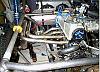 |
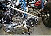
Here's all four tubes of the header welded and mounted
on the car. |
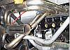 |
Another view - the radius rod that will mount the engine
will go through the center of the header. |
 |
One more view. A supertrapp muffler will be added to the end
of the header next week and sometime in the future the entire
assembly will be coated by Jet-Hot. |