20 August 2000
During the past couple of weeks, I've continued to prepare and install many of the smaller items - brakes, carb linkage, alternator mount, etc...
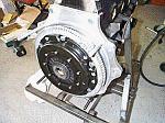
Mike and I removed the engine and assembled the flywheel, pilot
bearing, clutch disc and pressure plate. We had a fun time trying
to put the engine back into the rail without an engine hoist.
After about a half hour of struggling and cursing, I realized
that I had an early style pressure plate with a throwout bearing
collar and a late style transmission with a throwout bearing tube
- the collar would not slide over the tube. The problem was easily
solved by removing the collar from the pressure plate. Here's
the engine with the pressure plate, flywheel and clutch installed.
The collar is visible in the center of the pressure plate and
was removed before bolting the engine to the tranny:
Next comes the constant velocity joints and axles - I had them assembled and greased up and ready to install on the car and then realized that I had the wrong length axles, so, back to the store for an exchange.
Here's a closeup of the 930 c.v. joint: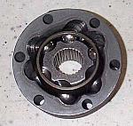
And the c.v. and boot on the axle: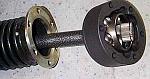
Finally, installed on the car: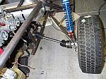
I picked up a General Motors 70 amp alternator and needed to
make a mounting bracked to fit the pinto engine. Here's a shot
of the beginnings of the mount: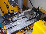
And the alternator mounting bracket on the engine, just below
the fuel pump blockoff plate.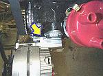
The brakes and clutch hydraulics are next, here's a shot of
the bent steel lines and throttle cable: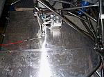
The shifter has been mocked up in this shot: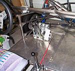
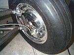
Here's some shots of the front brakes: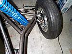
In between all this, I have been working on the carburetor
manifold and linkage. As with any project car, nothing fits like
it should, even those parts designed by the manufacturer to work
together. The carbs are 48mm weber dcoe sidedrafts and the butterflys
hit the manifold when actuated so a little porting was necessary: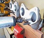
Then a suitable linkage had to be made to open both carbs at
the same time. I started by milling a flat area on the manifold
to which a plate can be bolted to support the linkage:
The manifold with the beginnings of the linkage:
I bored the holes in the linkage to accept sealed bearings,
made some arms and added some heim-jointed radius rods to activate
the carburetors and put the whole thing on the engine: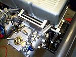 I still have to make a bracket
for the throttle cable and attach it to the throttle lever on
the linkage.
I still have to make a bracket
for the throttle cable and attach it to the throttle lever on
the linkage.
Air filter bases for these carbs seem to be non-existant, so
I had to modify a pair that were made for 44 mm downdraft carbs.
The bore needed to be enlarges and the bolt holes ovaled to fit
the sidedrafts: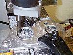
The gas tank and radiator have been mocked-up so I can begin
to design radiator tubes to carry coolant to and from the engine: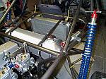
That's about all for this week, but here's a shot of a measuring
tape stretched across the front of the car: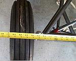
Yep, it reads 80 inches!
Aloha
| Previous | Project Sandrail Main | Next |